Design
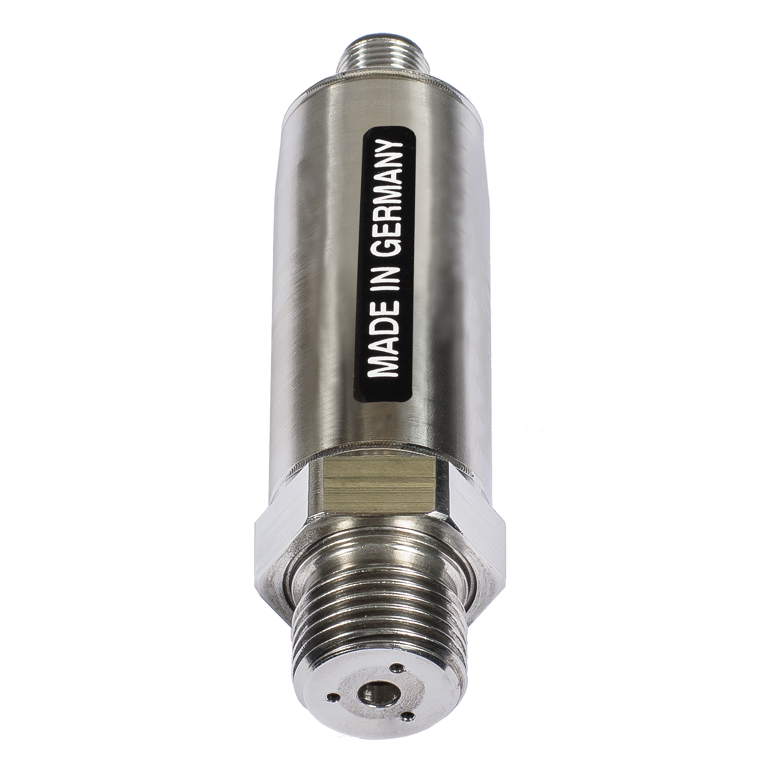
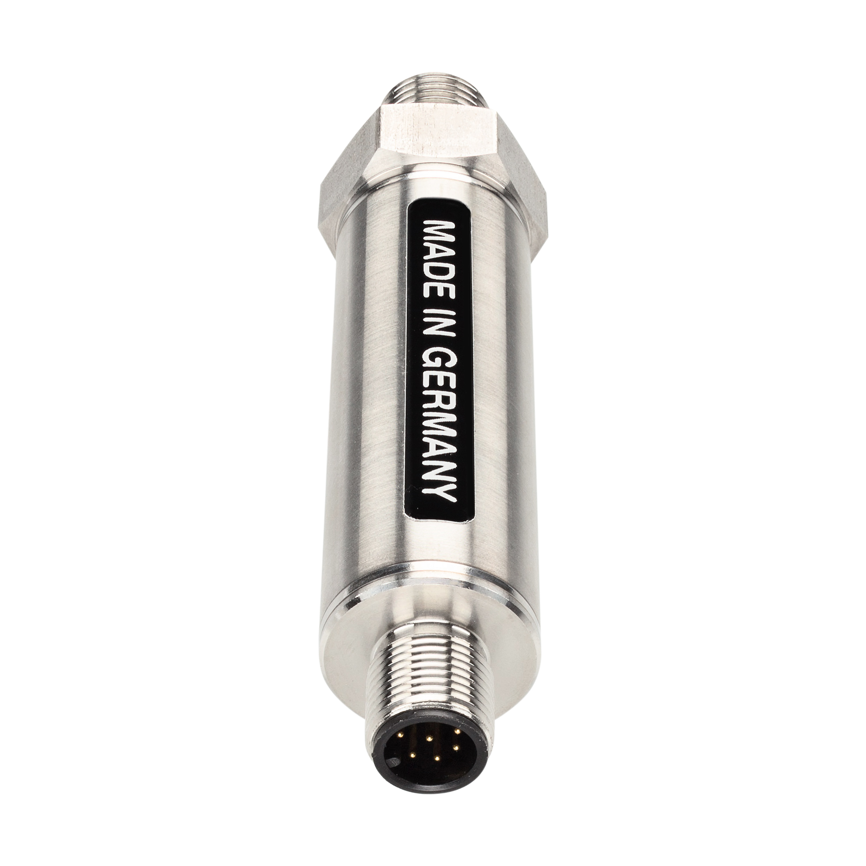
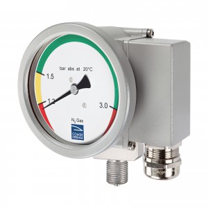
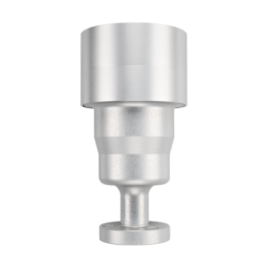
The gas density transmitter GDS-M consists of the following principal components:
- Tubular casing, stainless steel grade 1.4305
- Piezoresistive pressure sensor
- Electronic evaluation unit with microprocessor
- Pressure connection G 1/2″ or G 1/4″ (customized connections available)
- Electrical connection with circular connector M12x1
Operating principle
By way of its piezoresistive sensor, the gas density transmitter GDS-M continuously measures the gas density and temperature in the relevant gas chamber. The signals generated by the sensor are digitally compensated by the evaluation unit with microprocessor and presented as a high-precision output signal. The output signal is transmitted to a connected PC or the customer’s own diagnostic system. The measured values can then be used for documentation, trend analysis or other purposes.
Unlike electromechanical density monitors, which serve only as simple switches when the loss of SF6 violates set limit values, the GDS-M is capable of actively monitoring the gas density. The gas density transmitter also facilitates the monitoring of SF6 emissions from high-voltage systems. The GDS-M can likewise be programmed to monitor the density of other gases.
Measuring method
Based on the high-precision, digitally compensated pressure and temperature signals of the piezoresistive pressure sensor, the actual gas density is calculated with an optimal approximating polynomial for SF6 gas density. The correct density value is read out with a cycle time of 64 ms.
Fields of application
- Power supply facilities
- High-voltage and gas-insulated switchgear (GIS)
- Medium-voltage systems
- Indoor and outdoor gas-insulated transformers and generator circuit breakers
The information on this website represents the state of knowledge at the time of writing. Technical specifications are subject to modifications. Comde-Derenda GmbH accepts no liability whatsoever for the content provided or for damages resulting from the use of its products.

