Design
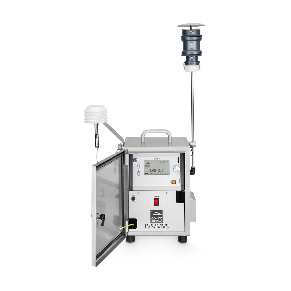
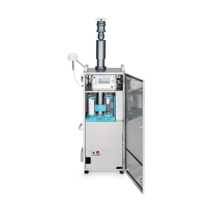
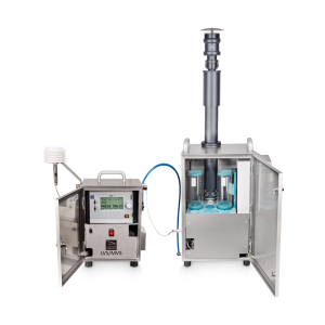
The low / medium volume samplers LVS and MVS consist of the following principal components:
- Stainless steel cabinet with lockable door
- Control unit with electronic modules, SD card reader and RS-232C interface
- Vacuum pump
- Orifice plate
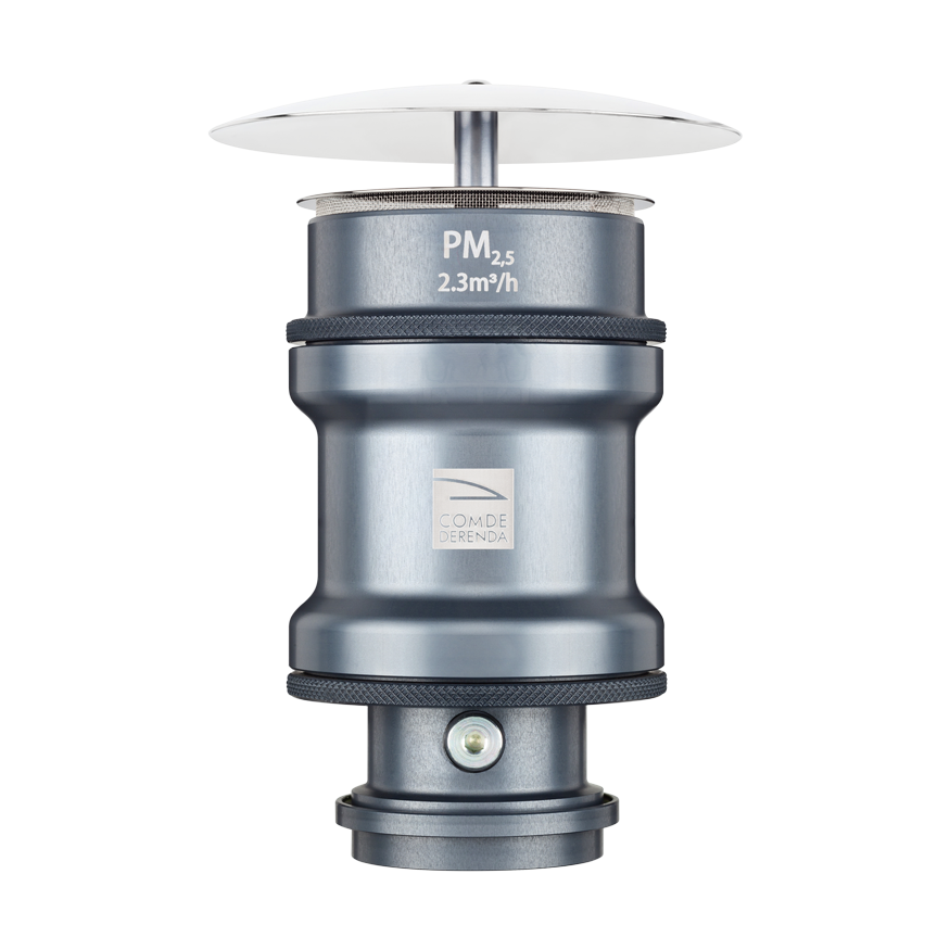
- Sampling inlet (for particulate matter fractions PM10, PM2.5 or PM1; optional)
- Intake tube, diameter 12 mm
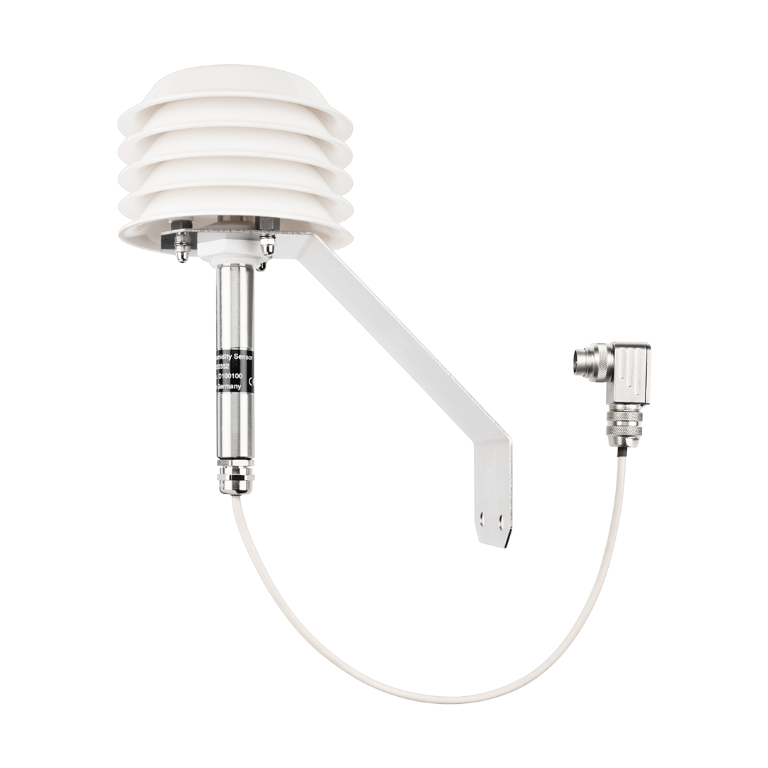
- Temperature and humidity sensors
The LVS and MVS use different vacuum pumps, which gives rise to the following specific characteristics:
LVS 3.1
The LVS 3.1 is equipped with a 4 m³/h rotary vane vacuum pump. The volumetric flow rate for sampling PM10 or PM2.5 fractions is 2.3 m³/h; the maximum vacuum at the filter is 300 mbar. The maximum volumetric flow rate when glass fiber filters are being used is 3.5 m³/h. When operating at maximum airflow, the functional aspects of the device are identical to those of its predecessor model GS 050/3-N, which is described on page 7 of VDI Guideline 2463. It also replaces the models GS 050/3-C, GS 050/3-G, GS 050-3D, LVS 3 and LVS 3D.
MVS 6.1
The MVS 6.1 is equipped with a 8 m³/h rotary vane vacuum pump and is otherwise identical to the LVS 3.1. It can be operated with a maximum volumetric flow rate of approx. 5.5 m³/h. It is especially suitable for measuring semi-volatile organic compounds (SVOCs) and for use in conjunction with special filter materials (e.g. cellulose nitrate or Nuclepore filters). The maximum vacuum at the filter is 500 mbar.
Operating principle
The desired settings are entered in the control unit before sampling begins. Once the operating cycle is activated, sampling takes place automatically according to the set parameters. During operation a vacuum pump draws air into the LVS / MVS through a sampling inlet. The device fractionates the dust particles by size with the aid of an upstream sampling inlet with impactor. The particles of the desired fraction are then deposited on a sampling filter. The volumetric flow rate is measured by an orifice plate situated between the filter and vacuum pump, and electronically adjusted with an accuracy of ≤ 2%. The ambient climatic conditions are continuously monitored by temperature and humidity sensors.
The following data captured during sampling are saved in the internal memory. The data can be additionally backed up on an SD card or transferred to a PC by way of the RS-232 interface:
- Serial number
- Filter number
- Sampling start and end date/time
- Sampling duration in hours and minutes
- Mean volumetric flow rate in m³/h and Nm³/h
- Sampled volume in m³ and Nm³
- Mean air pressure/temperature/humidity
- Mean pressure difference at the filter
- Filter storage temperature
Benefits
Our low volume samplers LVS and MVS were developed in 1976 and have been continuously improved in the intervening years. Numerous LVS/MVS units have been in constant use for many years.
Their operating reliability and quiet operation facilitates the troublefree collection of particle samples both in densely populated areas at any time of day or night, and indoors. Thanks to their small footprint, the units can be attached to masts or lampposts, for example, with suitable aids (platform).
Since the sampling inlet can also be operated at some distance from the unit, it can be installed in the immediate vicinity of the emission sources, typically for monitoring road traffic pollution. In view of their portability, the units can determine immission profiles for soot (elemental carbon (EC)) and other particulates by way of several permanent measurement stations.
As standard, the low volume samplers LVS 3.1 and MVS 6.1 are also designed as control units for the filter changer of the sampling system PNS. For further details, please consult the data sheet for the sampling system PNS.
The information on this website represents the state of knowledge at the time of writing. Technical specifications are subject to modifications. Comde-Derenda GmbH accepts no liability whatsoever for the content provided or for damages resulting from the use of its products.

